

These laws are more comprehensive than Ohm’s law and are used for solving electrical networks which may not be readily solved by the latter. Kirchhoff’s laws, two in number, are particularly useful
(a) in determining the equivalent resistance of a complicated network of conductors and (b) for calculating the currents flowing in the various conductors. The two-laws are :

Similarly, in Fig. 2.2 (b) for node A
(a) in determining the equivalent resistance of a complicated network of conductors and (b) for calculating the currents flowing in the various conductors. The two-laws are :
1. Kirchhoff’s Point Law or Current Law (KCL):
It states as follows :
In any electrical network, the algebraic sum of the currents meeting at a point (or junction) is zero. (or) The sum of the currents entering a junction is equal to the sum of the currents leaving the junction.
 |
| Fig.2.2 |
Consider the case of a few conductors meeting at a point A as in Fig. 2.2 (a). Some conductors
have currents leading to point A, whereas some have currents leading away from point A. Assuming
the incoming currents to be positive and the outgoing currents negative, we have
I1 + (−I2) + (−I3) + (+ I4) + (−I5) = 0
or I1 + I4 −I2 −I3 −I5 = 0 or I1 + I4 = I2 + I3 + I5
or incoming currents = outgoing currents
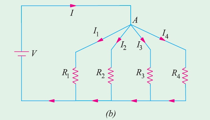
Similarly, in Fig. 2.2 (b) for node A
+ I + (−I1) + (−I2) + (−I3) + (−I4) = 0
(or) I= I1 + I2 + I3 + I4
We can express the above conclusion thus : ΣI=0
2. Kirchhoff’s Mesh Law or Voltage Law (KVL):
It states as follows :
The sum of the e.m.fs (rises of potential) around any closed loop of a circuit equals the sum of the potential drops in that loop.
(or) The algebraic sum of the products of currents and resistances in each of the conductors in any closed path (or mesh) in a network plus the algebraic sum of the e.m.fs. in that path is zero.
In other words, Σ IR + Σ e.m.f. = 0
algebraic signs of voltage drops and e.m.fs., otherwise results will come out to be wrong. Following
sign conventions is suggested :
(a) Sign of Battery E.M.F.
A rise in voltage should be given a + ve sign and a fall in voltage a −ve sign. Keeping this in mind, it is clear that as we go from the −ve terminal of a battery to its +ve terminal (Fig. ), there is
a rise in potential, hence this voltage should be given a + ve sign. If, on the other hand, we go from
+ve terminal to −ve terminal, then there is a fall in potential, hence this voltage should be preceded by a −ve sign. It is important to note that the sign of the battery e.m.f. is independent of the direction of the current through that branch.

Determination of Voltage Sign:
In applying Kirchhoff’s laws to specific problems, particular attention should be paid to thealgebraic signs of voltage drops and e.m.fs., otherwise results will come out to be wrong. Following
sign conventions is suggested :
(a) Sign of Battery E.M.F.
A rise in voltage should be given a + ve sign and a fall in voltage a −ve sign. Keeping this in mind, it is clear that as we go from the −ve terminal of a battery to its +ve terminal (Fig. ), there is
a rise in potential, hence this voltage should be given a + ve sign. If, on the other hand, we go from
+ve terminal to −ve terminal, then there is a fall in potential, hence this voltage should be preceded by a −ve sign. It is important to note that the sign of the battery e.m.f. is independent of the direction of the current through that branch.

(b) Sign of IR Drop
Now, take the case of a resistor (Fig.). If we go through a resistor in the same direction as the current, then there is a fall in potential because current flows from a higher to a lower potential. Hence, this voltage fall should be taken −ve. However, if we go in a direction opposite to that of the current, then there is a rise in voltage. Hence, this voltage rise should be given a positive sign. It is clear that the sign of voltage drop across a resistor depends on the direction of current through that resistor but is independent of the polarity of any other source of e.m.f. in the circuit under consideration.
For example: consider the circuit shown in Fig. below,
 The circuit has three active elements with voltages E1, E2 and E3. The polarity of each of them is
fixed. R1, R2, R3 are three passive elements present in the circuit. Currents I1 and I3 are marked
flowing into the junction A and current I2 marked away from the junction A with known information
or assumed directions. With reference to the direction of these currents, the polarity of voltage drops
V1, V2 and V3 are marked.
For loop1 it is considered around clockwise
+ E1 - V1 + V3 - E3 = 0
+ E1 - I1 R1 + I3 R3 - E3 = 0
E1 - E3 = I1 R1 - I3 R3
For loop2 it is considered anticlockwise
+ E2+ V2+ V3 – E3 = 0
+ E2 + I2 R2 + I3 R3 – E3 = 0
E2 – E3 = - I2 R2 - I3 R3
Two equations are obtained following Kirchhoff’s voltage law. The third equation can be written
based on Kirchhoff’s current law as
I1 – I2 + I3 = 0
With the three equations, one can solve for the three currents I1, I2, and I3.
If the results obtained for I1, I2, and I3 are all positive, then the assumed direction of the currents are
said to be along the actual directions. A negative result for one or more currents will indicate that the assumed direction of the respective current is opposite to the actual direction.
Now, take the case of a resistor (Fig.). If we go through a resistor in the same direction as the current, then there is a fall in potential because current flows from a higher to a lower potential. Hence, this voltage fall should be taken −ve. However, if we go in a direction opposite to that of the current, then there is a rise in voltage. Hence, this voltage rise should be given a positive sign. It is clear that the sign of voltage drop across a resistor depends on the direction of current through that resistor but is independent of the polarity of any other source of e.m.f. in the circuit under consideration.
For example: consider the circuit shown in Fig. below,

fixed. R1, R2, R3 are three passive elements present in the circuit. Currents I1 and I3 are marked
flowing into the junction A and current I2 marked away from the junction A with known information
or assumed directions. With reference to the direction of these currents, the polarity of voltage drops
V1, V2 and V3 are marked.
For loop1 it is considered around clockwise
+ E1 - V1 + V3 - E3 = 0
+ E1 - I1 R1 + I3 R3 - E3 = 0
E1 - E3 = I1 R1 - I3 R3
For loop2 it is considered anticlockwise
+ E2+ V2+ V3 – E3 = 0
+ E2 + I2 R2 + I3 R3 – E3 = 0
E2 – E3 = - I2 R2 - I3 R3
Two equations are obtained following Kirchhoff’s voltage law. The third equation can be written
based on Kirchhoff’s current law as
I1 – I2 + I3 = 0
With the three equations, one can solve for the three currents I1, I2, and I3.
If the results obtained for I1, I2, and I3 are all positive, then the assumed direction of the currents are
said to be along the actual directions. A negative result for one or more currents will indicate that the assumed direction of the respective current is opposite to the actual direction.
APPLICATIONS OF KIRCHHOFF’S LAWS:
Kirchhoff’s laws may be employed in the following methods of solving networks :
1. Branch-current method
2. Maxwell’s loop (or mesh) current method
3. Nodal voltage method.
1. Branch-Current Method:
For a multi-loop circuit the following procedure is adopted for writing equations :
1. Assume currents in different branch of the network.
2. Write down the smallest number of voltage drop loop equations so as to include all circuit elements ; these loop equations are independent.
If there are n nodes of three or more elements in a circuit, then write (n – 1) equations as per current law.
3. Solve the above equations simultaneously.
The assumption made about the directions of the currents initially is arbitrary. In case the actual direction is opposite to the assumed one, it will be reflected as a negative value for that current in the answer.
The branch-current method (the most primitive one) involves more labour and is not used except for very simple circuits.
2. Maxwell’s Loop (or Mesh) Current Method:
The method of loop or mesh currents is generally used in solving networks having some degree of complexity. Such a degree of complexity already begins for a network of three meshes. It might even be convenient at times to use the method of loop or mesh currents for solving a two-mesh circuit.
The procedure for writing the equations is as follows :
1. Assume the smallest number of mesh currents so that at least one mesh current links every element. As a matter of convenience, all mesh currents are assumed to have a clockwise direction.
The number of mesh currents is equal to the number of meshes in the circuit.
2. For each mesh write down the Kirchhoff’s voltage law equation. Where more than one mesh current flows through an element, the algebraic sum of currents should be used. The algebraic sum of mesh currents may be sum or the difference of the currents flowing through the element depending on the direction of mesh currents.
3. Solve the above equations and from the mesh currents find the branch currents.

Applying Kirchhoff’s voltage law to the two loops, we get
E1 – I1R1 – R3(I1 – I2) = 0
(or) E1 – I1(R1 + R3) + I2R3 = 0 ...Loop 1
Similarly, – I2R2 – E2 – R3(I2 – I1) = 0
– I2R2 – E2 – I2R3 + I1R3 = 0
(or) I1R3 – I2(R2 + R3) – E2 = 0 ...Loop 2
The above two equations can be solved not only to find loop currents but branch currents as well.
3. Nodal Voltage Method
Under this method the following procedure is adopted :
1. Assume the voltages of the different independent nodes.
2. Write the equations for each mode as per Kirchhoff’s current law.
3. Solve the above equations to get the node voltages.
4. Calculate the branch currents from the values of node voltages.
Let us consider the circuit shown in the Fig. below. L and M are the two independent nodes ; M
can be taken as the reference node. Let the voltage of node L (with respect to M) be VL.
Using Kirchhoff’s law, we get

I1 + I2 = I3
Ohm’s law gives I1 =V1/R1=(E1-VL)/R1
I2=V2/R2=(E2-VL)/R2
I3=V3/R3=VL/R3
E1-VL/R1 + (E2-VL)/R2 = VL/R3
Rearranging the terms, we get

It may be noted that the above nodal equation contains the following terms :
(i) The node voltage multiplied by the sum of all conductances connected to that anode. This term is positive.
(ii) The node voltage at the other end of each branch (connected to this node) multiplied by the conductance of branch. These terms are negative.
— In this method of solving a network the number of equations required for the solution is one less than the number of independent nodes in the network.
— In general the nodal analysis yields similar solutions.
— The nodal method is very suitable for computer work.
The method of loop or mesh currents is generally used in solving networks having some degree of complexity. Such a degree of complexity already begins for a network of three meshes. It might even be convenient at times to use the method of loop or mesh currents for solving a two-mesh circuit.
The procedure for writing the equations is as follows :
1. Assume the smallest number of mesh currents so that at least one mesh current links every element. As a matter of convenience, all mesh currents are assumed to have a clockwise direction.
The number of mesh currents is equal to the number of meshes in the circuit.
2. For each mesh write down the Kirchhoff’s voltage law equation. Where more than one mesh current flows through an element, the algebraic sum of currents should be used. The algebraic sum of mesh currents may be sum or the difference of the currents flowing through the element depending on the direction of mesh currents.
3. Solve the above equations and from the mesh currents find the branch currents.

Applying Kirchhoff’s voltage law to the two loops, we get
E1 – I1R1 – R3(I1 – I2) = 0
(or) E1 – I1(R1 + R3) + I2R3 = 0 ...Loop 1
Similarly, – I2R2 – E2 – R3(I2 – I1) = 0
– I2R2 – E2 – I2R3 + I1R3 = 0
(or) I1R3 – I2(R2 + R3) – E2 = 0 ...Loop 2
The above two equations can be solved not only to find loop currents but branch currents as well.
3. Nodal Voltage Method
Under this method the following procedure is adopted :
1. Assume the voltages of the different independent nodes.
2. Write the equations for each mode as per Kirchhoff’s current law.
3. Solve the above equations to get the node voltages.
4. Calculate the branch currents from the values of node voltages.
Let us consider the circuit shown in the Fig. below. L and M are the two independent nodes ; M
can be taken as the reference node. Let the voltage of node L (with respect to M) be VL.
Using Kirchhoff’s law, we get

I1 + I2 = I3
Ohm’s law gives I1 =V1/R1=(E1-VL)/R1
I2=V2/R2=(E2-VL)/R2
I3=V3/R3=VL/R3
E1-VL/R1 + (E2-VL)/R2 = VL/R3
Rearranging the terms, we get
It may be noted that the above nodal equation contains the following terms :
(i) The node voltage multiplied by the sum of all conductances connected to that anode. This term is positive.
(ii) The node voltage at the other end of each branch (connected to this node) multiplied by the conductance of branch. These terms are negative.
— In this method of solving a network the number of equations required for the solution is one less than the number of independent nodes in the network.
— In general the nodal analysis yields similar solutions.
— The nodal method is very suitable for computer work.


0 Comments